Shot Blasters are some of the toughest machines known to mankind. It is not uncommon to find 30, 40 and even 50 year old machines still running and in production. There are not many metal working machines around that can claim that.
Yet for all their toughness, they are also delicate. Not delicate in the sense that if you touch them they fall apart. Delicate in the sense that they need nursing along and require lots of TLC to get the best out of them.
The following 8 Ways will help you get the most out of your machine; more production, less downtime and less consumption costs.
8 Ways to Improve Wheel Blast Machine Performance:
- Ammeter
- Hot Spot Test
- Dust Collector Performance
- Separator Settings
- Abrasive Consumption Record
- Preventative Maintenance
- Abrasive Working Mix
- Blade, Control Cage and Impellor
1.Ammeter
The ammeter is your viewing window to performance of your blast machine. The ammeter indicates the quantity of abrasive being thrown by the blast wheel. As abrasive flow is increased to the blast wheel, the amperage consumed by the motor will rise. Conversely as abrasive flow is reduced to the wheel, the amps will drop.
All electric motors have have a full load amperage rating. This is the maximum amps that can be drawn for that particular motor.
Consult your machine operating manual or the motor data plate to determine the maximum amperage rating for your motor.
In most cases the machine will have been designed to run the wheels and motors at full load. The machine control panel will be fitted with ammeters to easily monitor the amperage being drawn.
Just a small reduction in full load amperage can have a big effect on the cleaning speed. So check to ensure maximum load is being used and the wheels are operating at 100% efficiency. Do not increase abrasive flow over the motor full load rating, as this will shorten the motor life.
In most cases a low amperage reading is the result of insufficient abrasive flow. However it can also signal wheel flooding. This is when the abrasive flow metering is opened too far, and excessive abrasive floods the wheel and prevents the motor operating and full speed or full amps.
If you are not sure if low amperage is the result of low abrasive flow or flooding, a simple test can quickly determine the cause.
1. Start the blast wheel and turn on the abrasive to the wheel. Run for a short while.

2. Close of the abrasive flow to the wheel and at the same time watch the ammeter.

3. If the amperage immediately drops, the cause is not enough abrasive flow.

4. If the amperage increases for 2-3 seconds and then drops, the cause is flooding.

5. Adjust and reduce the abrasive gate accordingly to set correct amperage.
During the blasting cycle the motor amps should remain consistent with only slight variations in the amperage reading. If the amperage reading is fluctuating wildly up and down it is a sure sign of inconsistent abrasive flow.
The most likely causes for this are either, not enough abrasive in the storage hopper (in this case when starting blasting the amperage will be stable, but after blasting for a short while it will start to fluctuate) or there is a blockage somewhere in the piping between the storage hopper and the wheel feed spout.
Always keep the abrasive storage hopper 2/3 full and clear any trash from feed pipes.
In order to run your machine at its maximum efficiency, monitor and maintain correct wheel amps settings.
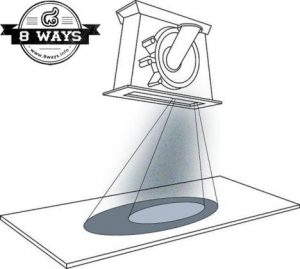
2. Hot Spot Test
The setting of the blast stream is one of the most important settings on your machine. If the thrown abrasive is not hitting the part correctly, the cleaning efficiency is sure to decrease. Natural wear on blastwheel internal parts will affect the position of the blast stream, so this is something that needs constant checking and re-adjusting.
Except in exceptional circumstances, ie you are dumb enough to climb inside a running machine, it is not possible to see the blast pattern of abrasive coming off the blastwheel. And if it is not visible, it can easily be out of adjustment, but unnoticed.
So in order to ensure the abrasive is hitting the right place, a Hot Spot test is performed. This is a simple test that uses heat to determine the where the main concentration of thrown abrasive is hitting the part.
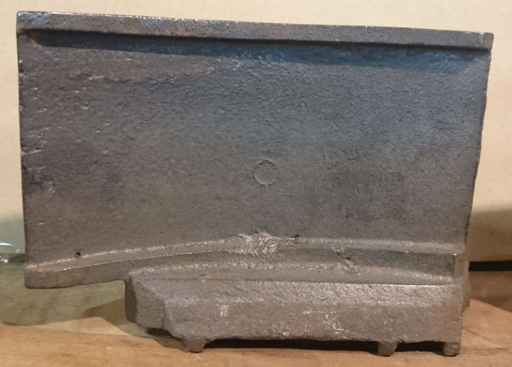
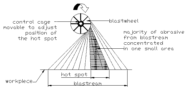
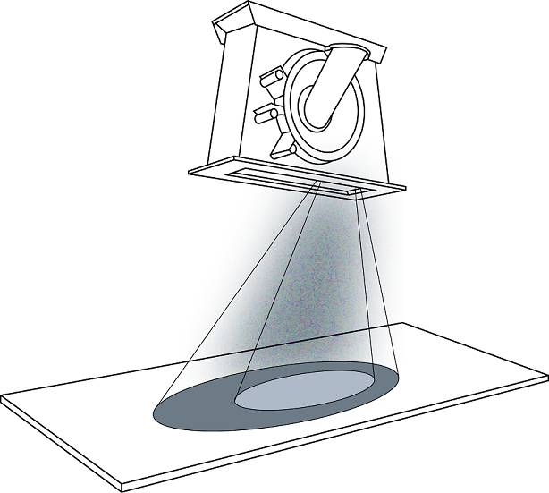
Refer to illustration 1. It can be seen that the majority of the abrasive thrown by the blastweel is concentrated in a relatively small area. Ahead and behind this concentration lesser abrasive is thrown. This is a function of all correctly designed blast wheels.
This area of higher abrasive concentration should be blasting onto the part, and blasting onto the the correct area of the part. If it is missing the part and blasting the cabinet wall, or blasting the wheel housing liners, production rates will decrease and abrasive and wear costs will increase.
Get it right, or you are throwing money down the drain.
When the blast stream hits a stationary work piece the area of concentrated blast will generate heat. This is referred to as the “Hot Spot”.
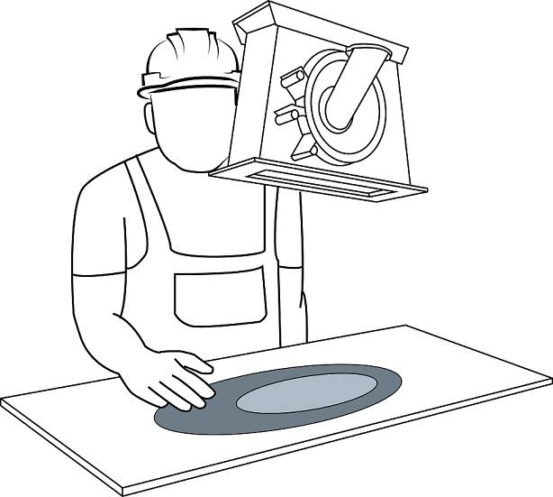
The Hot Spot test involves placing a plate (or other steel object depending on the machine configuration) in front of the blast stream and blasting it for 1 minute, with the test plate stationary.
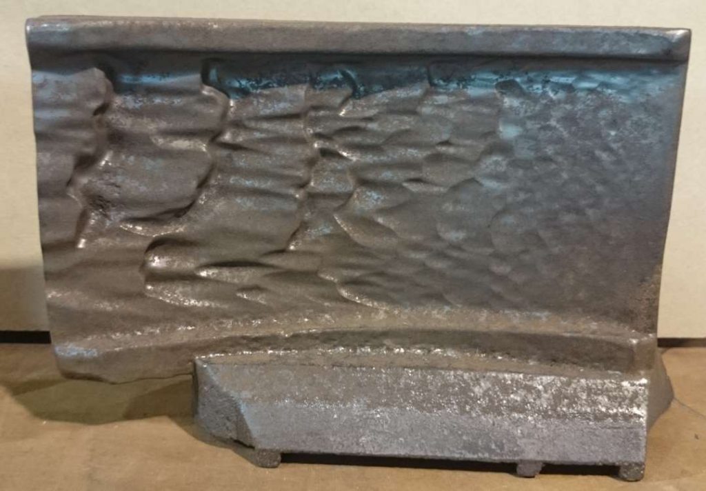
By running your hand over the area just blasted it is easy to determine the hottest area, see illustration 2. This is the Hot Spot. Determining this indicates where the concentration of the blast stream is. The control cage can now be adjusted accordingly to get the Hot Spot in the correct position.
Remember a small adjustment in the control cage can have a big effect on the Hot Spot position, so don’t over adjust.
Generally several tests are conducted. Blast, feel, adjust. Test again. Rinse and repeat until the correct setting is found.
Once the correct Hot Spot position is established it should be regularly checked. Just a small amount of wear on wheel parts can throw out the Hot Spot alignment.
3. Dust Collector Performance
Blasting is inherently a dusty process. With a correctly designed and functioning dust collector, the dust emitted from the machine can be reduced to zero.
The dust collector has to perform 2 jobs simultaneously. Firstly is to remove airborne dust from the blast cabinet as the machine is in operation. Secondly is to provide the vacuum airflow for the airwash separator, to suck out dust from the recycling abrasive.
The majority of dust collectors in use today are cartridge type, using reverse pulse cleaning. The most common problem with them is the filters blocking. Too much dust blocking the filter cartridges reduces the suction airflow created by the fan. Once this happens things become dusty and dirty very quickly.
The dust collector can be monitored during use and problems rectified before the filters block. A magnehelic differential pressure gauge should be fitted to the dust collector. If there is not one, it is cheap and simple device to fit. As the name suggests, this gauge measures the pressure difference between the clean and dirty side of the filters. As the filters block with dust the pressure difference increases.
When running correctly, the pressure difference should be 2-8″ WG (50-200mm WG). Higher readings indicate the filters are severely blocked.
The most likely cause of filter blockage is a problem with the reverse pulsing system. If the pulsing does not function correctly the dust is not adequately cleaned from the filter cartridges, leading to blockage.
Fortunately reverse pulsing systems are easy to trouble shoot. No special tools are required, only a pair of ears. When working correctly there should be a distinctive pulsing sound every 20-30 seconds.
If there is not, the following should be checked:
1. If there is no sound and no pulsing, the most likely cause is electrical

2. If there is weak or no pulsing, and a constant hissing sound of compressed air, there is a leak in one of the valves.

    This will be either:

        a. leaking diaphragm in the pulse valve

        b. broken or loose hose from solenoid valve to pulse valve

        c. faulty solenoid valve

        d. loose or leaking fitting on pulse or solenoid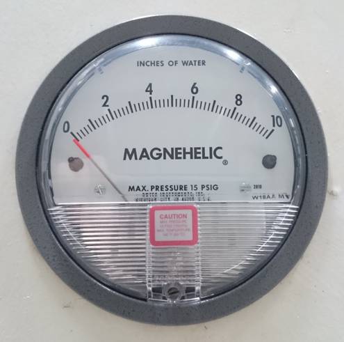
There is another model called photohelic. That version also has electrical outputs that can be used to trigger alarms or warning lights when the preset differential pressure is too high or too low.
The filter cartridges in these dust collectors are made from various cloth or cellulose materials. All these materials are absorbent. Any moisture or water present will be soaked up by the filter material. Once the filters are wet, the dust sticks to them and it is very difficult to dislodge.
This is another cause of filter blockage. The reason is the compressed air used for the reverse pulse cleaning is not sufficiently dry. This air must be perfectly dry and passed through a refrigerated or air regenerative desiccant drier prior to entering the dust collector.
The water vapour in undried air is impossible to see. So even though water might not be visible or present, it does not mean the pulsing air is dry. Only by passing through an air drier can you be sure the air is actually dry.
4. Separator Settings
Improper settings or malfunction of the abrasive separator will result in incorrectly sized and or dirty abrasive being returned to the abrasive storage hopper. This will lead to reduced cleaning speeds, excessive wheel wear, contaminated work pieces and higher abrasive consumption.
Most, but not all, abrasive separators are fitted with a rotary scalping drum. This unit is to remove oversize waste from the abrasive. Any holes or damage to the rotating mesh will allow over size particles to pass through with the good abrasive. Blockage of the mesh screen will result in good reusable abrasive being discharged with oversize waste.
After passing through the rotating screen, reusable abrasive and dust fall through the air wash zone. Here the dust and fine particles are separated from the good abrasive. Efficient removal of fines, dust, mil scale and sand is crucial to reducing part wear. Even a small 2% fines contamination can increase wear on parts dramatically.
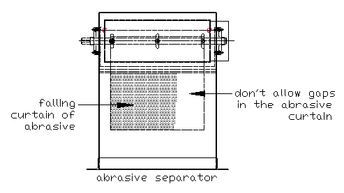
A strong vacuum airflow is pulled through the falling curtain abrasive. Fine and light weight particles are sucked out, whilst good heavier abrasive drops into the storage hopper.
To function correctly it is important the curtain of falling abrasive is stretched completely over the width of the separator. The vacuum airflow will take the path of least resistance. Any gaps in the abrasive curtain will allow the airflow to divert around the curtain instead of pulling through it. This reduces the efficiency of dust separation. See below illustration. If full curtain is not obtained, adjust the metering plate to decrease abrasive flow into the airwash zone.
To check separator for correct function the following should be regularly checked:
1. Check oversize waste drum for good abrasive. A small amount is likely to be present. Large amounts indicate rotary screen blockage.

2. Check dust collector waste bin for good abrasive. Adjust power of airflow to the dust collector with the slide gates fitted to the ducting.

3. Perform working mix test on the abrasive in the storage hopper. Too big or too small abrasive sizing indicates incorrect separator setting. (do not do this test immediately after adding a large amount of new abrasive).

4. Check fines waste drum for good reusable abrasive. Adjust skipper plates in separator if excessive good abrasive is present.
With routine inspection, monitoring and adjustment the separator can consistently provide clean, correctly sized, abrasive to the blastwheels. This will increase parts life, reduce abrasive consumption and increase quality of the surface finish.
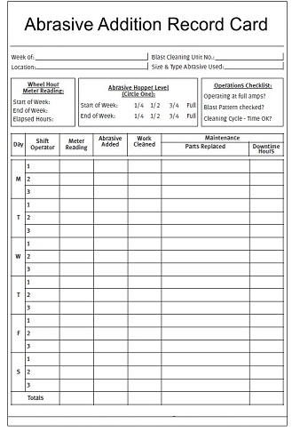
5. Abrasive Consumption Record
An excellent way to monitor the performance of your machine is to keep an abrasive consumption record. This involves tracking how much abrasive is added to the machine and how much product is blasted, measured by weight or area.
This is an effective way to get a true measurement of your blasting costs. The abrasive consumption record will also provide an early indication if something is not right with the machine. After a bench mark is established, a sudden spike in abrasive consumption is the first warning sign something is not right.
Once the machine is running continuously and smoothly, good practice is to continuously add small amounts of new abrasive to replenish the abrasive that has broken down during use.
Bad practice is to run the machine until the storage hopper is almost empty and then to add a large amount of new abrasive. This results in lower production rates and an immediate coarser finish on the parts. Accurate abrasive consumption is also difficult to monitor.
To obtain a stable and optimum performance from your machine, small additions of abrasive should be added in short regular intervals. For example, if the abrasive consumption is 200kg/lbs per day, the recommended method of addition is to add 25kg/lb per hour as the machine is in operation.
This is better than adding 200kg/lb at the beginning or end of the shift. By incorporating the recommended addition method, the abrasive working mix and resulting surface profile will remain consistent.
Initially it will take some trial and error and experimenting to establish the correct addition amount. During the trial period the abrasive storage hopper level and fines and dust take outs should be monitored and new abrasive additions adjusted to match the requirements.
Once the abrasive consumption is established a daily record can be kept.
6. Preventative Maintenance
As the days, weeks and months go by, and your blasting machine is running well and churning out production, small problems can appear that go unnoticed.
Unfortunately, with this type of equipment, small faults left unchecked, can quickly become a big failure. And breakdowns can cost a lot to fix, and create production down time if the failed item is not readily available. So our objective is to prevent these breakdowns in the first place.
Up to the challenge steps our hero, Preventative Maintenance. This should be performed daily, weekly, monthly, half yearly and yearly. We like to use simple check lists for each of the different maintenance checks. This keeps it quick, simple and easy for operators to perform.
The objective of preventative maintenance is:
~ To prevent breakdowns

~ To anticipate repairs by locating probable causes

~ To plan repairs for convenient times

~ To detect and fix minor repairs to prevent major ones

~ To be certain that the equipment is being operated safely and at the highest possible efficiency

~ To keep an accurate record of maintenance activity and replacement parts usage in order to manage spare parts inventory and monitor operating and maintenance costs.
Items to check, monitor and include in check lists include the following:
»   Visual inspection
»   Fan vibration check
»   Bearing temperature monitoring
»   Electrical drive motor temperature monitoring
»   Differential pressure readings
»   Cleanliness of filters
»   Adjustment and alignment of belt tightness
»   Monitoring of general wear and tear
»   Lubricating oil level
»   Greasing of bearings
»   Clean out of foreign objects and trash
»   Calibration of fume level detectors
»   Electric circuit stability
»   PLC fault audit and rectification
As Benjamin Franklin wisely advised; “An ounce of prevention is worth a pound of cure.” Obviously he had a blasting machine and had learnt the hard way.
Set up a Preventative Maintenance Program, and you will both improve your production output and reduce or prevent downtime.
7, Abrasive Working Mix
Do you know what is the best abrasive size to use? Big? Small? Well there is no single answer as it depends on the application. This is why abrasive is available in a variety of sizes.
Regardless of the application, or equipment set up, the rule of thumb is to use the smallest possible abrasive size that will do the job of cleaning the part, and produce the required surface profile and finish. Although counter intuitive, this is a fact as smaller abrasive blasts faster.
Anyhoo, this is subject of another 8 Ways. The subject of this 8 Ways is the “abrasive working mix”.
For cost and production effective blasting we need a balanced abrasive working mix. This is a combination of large, medium and small abrasive particles in the machine.
If all the particles were exactly the same size the cleaning efficiency would be reduced. This mixture of abrasive sizes is referred to as the “working mix”. A balanced working mix will have the correct proportion of different size particles in it.
When a variety of particle sizes are present, each size performs a specific function. The larger particles have the kinetic energy to either knock and break off whatever is being removed from the surface, ie millscale, paint, rust etc. The smaller particles then perform the cleaning action and scour the surface and get into every nook and cranny to thoroughly clean the surface.
There is no cost involved in controlling the working mix, just the knowledge of how to control the abrasive going in (as new abrasive) and out (as dust) of the machine.
We have spoken before of the importance of adding small regular additions of new abrasive to the machine to replenish consumed abrasive. The abrasive working mix works hand in hand, and is a consequence of, this.
The working mix test is a simple measurement of the proportion of new vs used abrasive in the machine.
The method of manufacturing steel abrasives produces a wide variety of grain sizes. This mixture of sizes is divided into approx. 10 separate groups of similar sized shot and grit particles; S070 – S780 steel shot and G120 – G14 steel grit.
Within each abrasive size there is also a range of particle sizes, ie the particles in S330 steel shot range in size from approx. 0.71 to 1.18mm. SAE specifications stipulate the sizes, and proportion of big and small grain sizes in each size. In the case of S330 the specification is; nothing bigger than 1.4mm, no more than 5% bigger than 1.18mm, at least 85% bigger than 0.85mm and at least 97% bigger than 0.71mm. Sounds more complicated than it really is.
This is the size of the abrasive when it is new. Obviously as soon as it starts to be used it is going to decrease in size. It cannot get bigger.
All abrasive sizes have a minimum 85% size within them. This is the reference size for checking the working mix. The working mix check is to determine what percentage of the abrasive in the machine can still be retained on this reference screen.
A good working mix range is 30 – 50%. So how to check? Easy. Again using S330 as an example, we know reference size is 0.85mm. This is the screen size we will use for the test. You can refer to SAE steel abrasive standards to determine the reference size for the abrasive size you are using.
- Purchase a small 0.85mm mesh hand sieve.
2.Take a sample of the abrasive from the machine storage hopper. Most accurate way is to capture the abrasive as it falls from the separator into the storage hopper. - Now weigh the sample. Record the weight.
- Pour the sample into the sieve. Shake until all small particles pass through sieve.
- Gather all remaining particles that have been retained on top of the sieve and weigh.
- Finally calculate what percentage of the original sample is retained on the screen – retained on screen / original weight x 100 = %
Worked example:
- Sample collected weighs 167 grams
- After sieving the weigh of the sample retained on the mesh is 69 grams
(69/167)*100= 41.3%. Perfect score. (remember a good working mix is 30-50%)
Now lets assume we get a different reading:
- Sample collected weighs 167 grams
- After sieving the weigh of the sample retained on the mesh is 124 grams
(124/167)*100= 73.4%. Far from perfect score. This indicates the proportion of large abrasives in the machine is too high. There could be several causes of this:
A. A large amount of new abrasive recently added to the machine
B. Separator or dust collector malfunction. Too many small abrasives are being removed from the machine. Maybe separator is not set correctly or dust collector is sucking too hard.
And yet another reading:
- Sample collected weighs 167 grams
- After sieving the weigh of the sample retained on the mesh is 22 grams
(22/167)*100= 13%. Again a far from perfect score.
That means in the working mix 87% of the abrasive is below the reference size. If the abrasive is this fine you would have probably noticed by now anyway. Maybe the blasted parts are very dusty or the surface roughness profile has dropped dramatically. This reading indicates there is far too much fine abrasive in the machine. Possible causes:
A. No addition of new abrasive for a long time. So the abrasive in the machine is just getting smaller and smaller.
B. Dust collector blocked or not working and not removing fines and dust.
C. Separator air wash zone blocked.
So regardless of the size of abrasive you use, there is an optimum size range (working mix) that should be maintained in the machine. Monitor and maintain this and you will achieve maximum blasting output and consistent surface profile and finish.
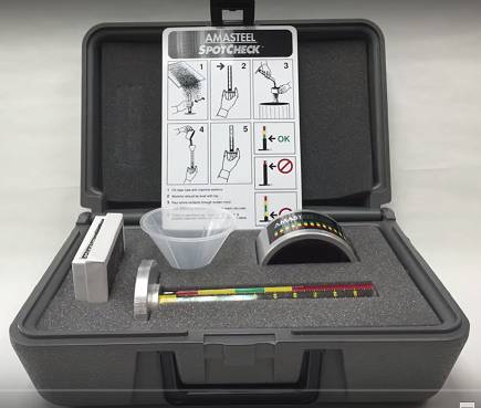
If you use several abrasive sizes or want a ready made tester, a working mix test kit is available.
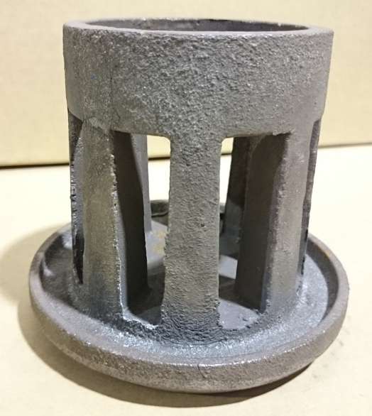
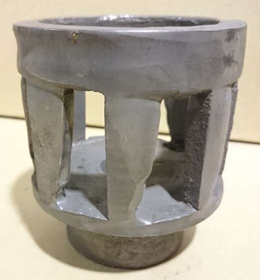
8. Blade, Control Cage and Impeller Wear
The parts subject to most wear in a wheel blast machine are the wheel feed parts. These control, direct and throw the abrasive onto the workpiece. All that high velocity passing through them creates wear and tear, can’t be helped. So they need regular checking and adjusting in order to keep your machine running at its best.
The blades are critical in throwing the abrasive onto the work piece. As each slug of abrasive leaves the control cage and impeller, it lands on the front face of the blade and slides down its length until being thrown at tremendous speed onto the work piece. Obviously, in order for this to be effective, the abrasive needs to slide down a smooth flat surface.
Over time the blades will wear out. As they wear the surface roughens and impedes the travel of the abrasive particles. This interference slows down the abrasive and creates scattered abrasive patterns. This is very noticeable with badly worn and pitted blades. The abrasive gets hooked up in the pits and thrown around randomly. Ironically one of the biggest causes of badly worn blades is high amounts of fines waste in the abrasive.
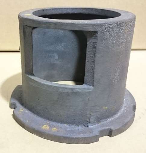
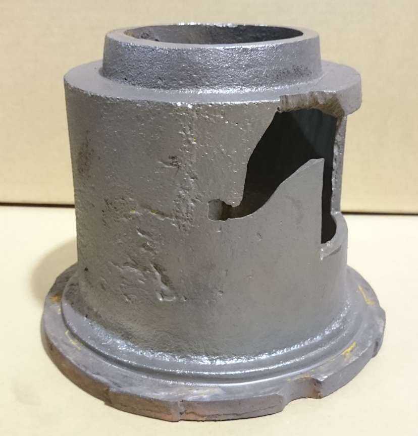
The control cage determines the position of the blast stream as it comes off the wheel. The control cage is adjustable allowing the blast stream to be moved into the correct position. Rotating the control cage by just 10mm can move the blast stream by up to 300mm.
Although manufactured from a hard metal, the constant flow of abrasive through the control cage creates wear. This wear has the same effect as adjusting the control cage. As it wears, so the blast stream moves. The control cage must be regularly checked and readjusted to compensate for this wear. Without readjustment the blast stream will creep out of its correct position, and instead of blasting the parts will blast the end liners.
The impeller releases measured slugs of abrasive onto the front face of the blades. Unlike the control cage, which is adjustable, both the impeller and blades are held in a fixed position onto the wheel hub. The alignment of the impeller opening to its corresponding blade is critical in maintaining the correct blast pattern.
As the impeller fingers wear, the abrasive is released onto the ends of the blades, rather than onto the front face. Now, instead of a smooth flow down the front of the blade face, the abrasive is ricocheting around with a scattergun effect. This creates additional wear on liners and reduces the production rate.
The blades, control cage and impeller should be regularly checked, adjusted and, if necessary, replaced. It is false economy to continue blasting with worn our parts. Incidental machine wear costs and loss of production far out weigh the cost of replacement parts.