

Once, when we were a blasting and painting contractor, we faced many many problems with dust leakage from our blastroom and wheel blast machines. Our neighbours continually complained about us and reported us to the environmental authorities.
We faced numerous quality issues with dust sticking to the surfaces of freshly painted parts, resulting in lots of qc rejections. And our work place was always shrouded in a dusty haze with a layer of fine black dust settled on every imaginable surface.
The root cause of all our problems was the condition of dust collectors fitted to our blast machines. Although our blasting equipment was in acceptable condition the dust collectors were not performing or operating efficiently to remove enough dust. Most of the time they seemed to be half choked up with dust. Whatever dust was being removed was going straight out the exhaust chimneys (much to our good neighbours horror).
After implementing a series of repairs, and regular maintenance, the dust problems disappeared overnight.
Follow the enclosed 8 Ways and you will be well on the way to ensuring you do not face the same problems.
8 Ways to Run Your Dust Collector At Max Performance:
- Pulsing System
- Pulse Cleaning Air
- Magnehelic Gauge
- Pulse Cleaning Duration & Interval
- Balanced Airflow & Dust Buildup
- Dust Leakage Through Filters
- Air Leakage Through Dust Bin
- Fan & Belt Maintenance
1. Pulsing System
Blasting is inherently a dusty process. With a correctly designed and functioning dust collector, the dust emitted from the machine can be reduced to zero.
The majority of dust collectors in use today are cartridge type, using reverse pulse cleaning. The most common problem with them is the filters blocking. Too much dust blocking the filter cartridges reduces the suction airflow created by the fan. Once this happens things become dusty and dirty very quickly.
The most likely cause of filter blockage is a problem with the reverse pulsing system. If the pulsing does not function correctly the dust is not adequately cleaned from the filter cartridges, leading to blockage.
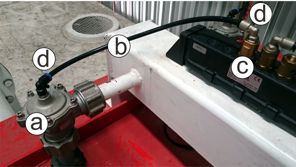
Fortunately reverse pulsing systems are easy to trouble shoot. No special tools are required, only a pair of ears. When working correctly there should be a distinctive pulsing sound every 20-30 seconds.
If there is not, the following should be checked:
- If there is no sound and no pulsing, the most likely cause is electrical
- If there is weak or no pulsing, and a constant hissing sound of compressed air, there is a leak in one of the valves.
This will be either:
- leaking diaphragm in the pulse valve
- broken or loose hose from solenoid valve to pulse valve
- faulty solenoid valve
- loose or leaking fitting on pulse or solenoid
will be the same.
2. Pulse Cleaning Air
Wet pulsing air. The enemy of all dust collectors using a reverse pulsing system to clean the filters. The most common dust collector in the blasting industry are cartridge type. These dust collectors are fitted with pleated filter cartridges made from a variety of materials, usually cellulose and or polyester. These materials are highly absorbent.
Any moisture or water in the pulse cleaning air supply will be soaked up by the filter material. If the filters become damp, the dust sticks to them and is very difficult to dislodge. Once this happens the filters block and the dust collector effectiveness is drastically reduced.
The water vapour in undried air is impossible to see. So even though water might not be visible or present, it does not mean the pulsing air is dry. Only by passing through an air drier can you be sure the air is actually dry.
The pulsing air must be perfectly dry and passed through an air drier prior to entering the dust collector. Blasting consumes huge amounts of compressed air. Even if the whole air supply is not dried, a small drier can be fitted to the dust collector air supply to ensure at least the pulsing air is dry. Reverse pulse dust collectors only consume small amounts of compressed air, approx. 30cfm.
There are a variety of air drier types available. Different types dry the air to varying degrees. For the purposes of reverse pulse cleaning dust collectors a refrigerant type air drier is sufficient. These electric powered units reduce the compressed air dew point to approx. 36ºF (2ºC). This will ensure the air is dry enough to pulse clean the filters without dampening the filter material.
Photos courtesy of KAESER Kompressoren.
3. Magnehelic Gauge
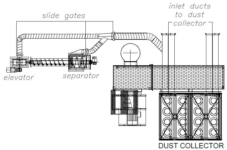
The dust collector has to perform 2 jobs simultaneously. Firstly is to remove airborne dust from the blast cabinet as the machine is in operation. Secondly is to provide the vacuum airflow for the airwash separator, to suck out dust from the recycling abrasive.
Blocked filter cartridges reduce the effectiveness of both these. The dust collector can be monitored during use and problems rectified before the filters block. A magnehelic differential pressure gauge should be fitted to your dust collector.
If there is not one, it is cheap and simple device to fit. As the name suggests, this gauge measures the pressure difference between the clean and dirty side of the filters. As the filters block with dust the pressure difference increases.
When running correctly, the pressure difference should be 2-8″ WG (50-200mm WG). Higher readings indicate the filters are severely blocked.
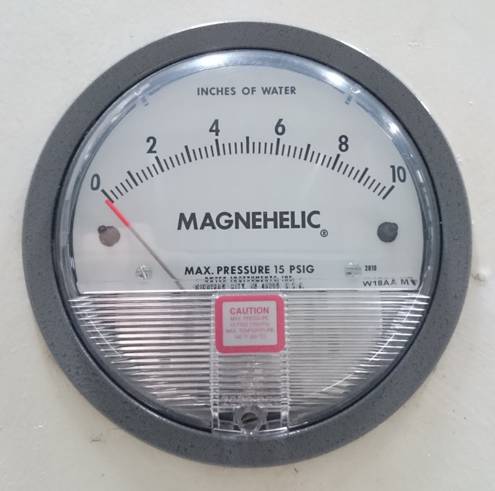
This is the standard magnehelic gauge we always use on our equipment. This model only provides a visual analog reading of the differential pressure.
There is another model called photohelic. That version also has electrical outputs that can be used to trigger alarms or warning lights when the preset differential pressure is too high or too low.
4. Pulse Cleaning Duration & Interval
Every time it activates, the pulse cleaning system on your dust collector is not supposed to sound like a jumbo jet screaming down a runway. It should sound like a clap of thunder. More is often better. In the case of pulse cleaning, less is better.
Each time the pulsing activates to clean the filter cartridges it should emit only a short sharp bang. If the air flow through the pulsing nozzle drags on and on it is counter productive. It does not clean the filter any more and just reduces the life of the filter cartridge.
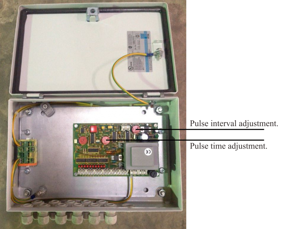
Pulsing interval is the time between cleaning pulses. There is no hard and fast rule for this setting. Usually the gap between pulses is determined by trial and error. Pulsing should be timed to keep the filters differential pressure between 50-200mm WG, in old money that is 2-8″ WG. All our dust collectors are set at an initial pulsing interval of 15 seconds. This seems to work well in most instances.
The pulse cleaning sequencer fitted to most dust collectors cleans the filters one by one, starting from the first filter to the last, before starting at the beginning again. So bear in mind the more filters there are, the longer it will take for the cycle to complete before getting back to the first filter again. This needs to be taken into consideration when setting the pulsing interval. Generally there will be a longer gap between pulses on dust collectors with lesser filters.
Your pulse controller is probably not the same as this one. But the functions are generally the same.
More sophisticated systems also start and stop the pulsing on demand, depending on filter differential pressure.
5. Balanced Airflow & Dust Build Up
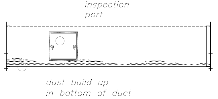
A hidden danger lurks in many a dust collector inlet ducting. And that is the build up of dust in duct, that goes unnoticed. This can occur when there has been a problem with the dust collector. At some time maybe the filters have become blocked or there has been an issue with the fan performance. This results in a reduction of suction power.
In turn this results in a drop of air velocity in the ducting. If the air velocity drops the dust carrying capacity of the air flow is reduced. If reduced too much dust will drop out of the air stream and settle in the bottom of the duct. And there it can sit even after the dust collector is fixed. If the dust collector is continuously under performing this dust will continue to build up in the duct.
During installation any ducting supports will have been designed to support the ducting. Unlikely they were designed to also support hundreds of kilograms/pounds of dust. Most blasting is performed on steel parts. And the most commonly used abrasive is steel grit or shot. This means the dust is relatively heavy. Over time the weight can build up until ultimately the duct collapses.
Easy solution is to fit inspection ports and schedule checking during preventative maintenance.
Whether used on a blastroom or wheel blast machine, often there are branches in the ducting to various parts of the machine ie, cabinet, vestibules, elevator, separator etc. It is important these are kept in balance and the correct amount of air is passing through them according to the design. This ensures each part of the machine is being ventilated correctly. Ducting gates can wear out or loosen over time, and that effects the airflow.
The method to check the airflow volume is to measure the air velocity through the duct. Air velocity should be approx. 3, 500ft/min in most situations. Slower than this the dust will not be conveyed. Faster than this creates excessive wear on the ducting.
6. Dust Leakage Through Filters
Dust leaks through the dust collector will be obvious. Even a small leak can produce a distinctive dust cloud. But often finding the source of the leak is not so easy. Inside the dust collector everything is dusty and looks the same.
Most common sources of dust leakage we have come across are as follows:
1. filter cartridge cell plate weld cracked
2. filter cartridge damaged
3. rubber gasket on end of filter not tight enough or damaged
4. rubber O ring missing from bolt end of filter cartridge
Item 1 is not common and is easy to trace from the clean side of the cell plate. Easy to rectify.
Item 2 is also relatively easy to detect. Usually it will be only one filter cartridge that is damaged. As most filter material is white, the filter will show obvious signs of dust passing through it. The metal end caps of filter cartridges are glued into place. Incorrect glue application can lead to leakage.
The two most common causes are items 3 and 4.
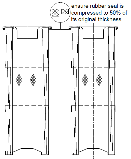
Item 3. Filters are fitted with a rubber sealing band that is compressed against the cell plate. To obtain a tight deal the filter should be tightened to reduce the rubber sealing band by 50%. This amount of compression provides a tight seal. If dust is still leaking through this area, the rubber seal maybe damaged.
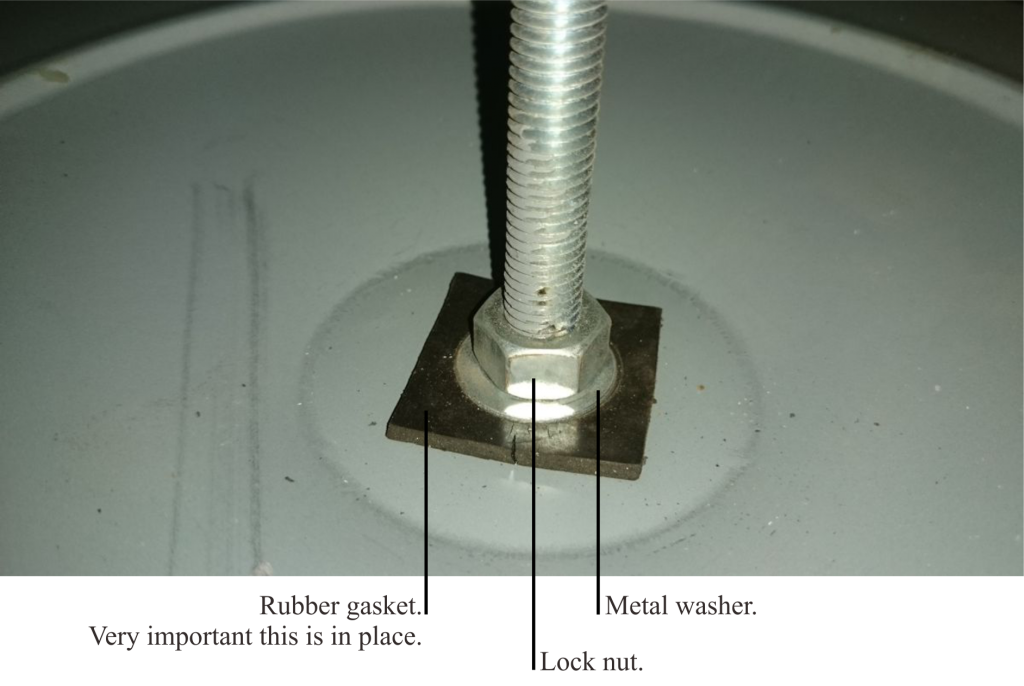
Item 4, the most common cause of dust leakage. A threaded tie rod passes through a hole in the filter end plate. Unless properly sealed the tiny gaps around this hole will allow dust to pass through. The correct sealing is to have a rubber washer sandwiched between a flat washer and the filter end plate. Often these rubber washers become lost or damaged during filter changes. Easy to make replacements from 3mm (1/8″) thick rubber.
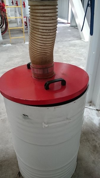
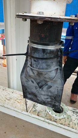
7. Air Leakage Through Dust Bin
This is a common problem we often come across that can greatly reduce the efficiency of your dust collector. Air leaks around the dust outlet. All dust collectors are fitted with a discharge hopper. After dust has been pulsed off of the filter it will find its way into the hopper prior to discharge, usually, into a drum or bin.
The dust collector may or may not be supplied with some kind of shut off valve on the bottom of the hopper. If it is keep it closed until necessary to open to discharge the dust. If no shut off valve is fitted ensure there is a tight seal between the discharge hopper and the waste drum.
Over time rubber or sponge seals become worn. Once this occurs air is sucked in through any gaps. Air sucked in here is air that is not being sucked through the blasting system, which is where it should be coming from. The air flow will take the path of least resistance and gaps between hopper and waste bin is the path of least resistance.
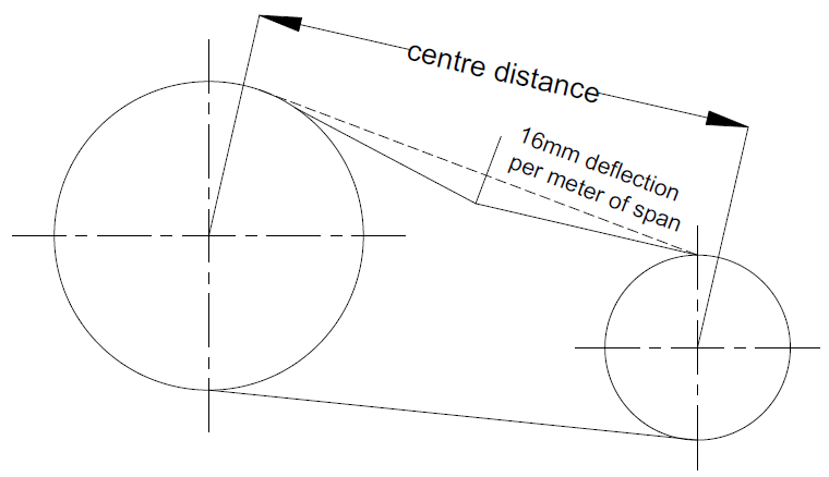
8. Fan & Belts Maintenance
Last one, the fan. Slipping belts don’t suck. Keep the fan belts tight and the fan in balance. Loose belts reduce airflow.
Under normal circumstances, handling clean air, the fan should require cleaning only about a year. However, the fan and system should be checked at regular intervals to detect any unusual accumulation. The fan impeller should be specially checked for build-up of material which may cause an imbalance with resulting undue wear on bearings and belt drives.
A regular maintenance program should be established to prevent material build-up. Periodic inspection of the rotating assembly must be made to detect any indication of weakening of the rotor because of corrosion, erosion, or metal fatigue.
Failure to do so can result in serious bodily injury or death.